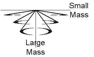
Mass responded to an attraction force at its center. The attraction force had two manifestations, the gravitational force on radial motion and the inertial force on rotational motion. The inertial force caused tangential motion perpendicular to the radius. The spiraling motion had a path with positive curvature away from linear tangential speed (i.e. an attraction force toward the center of rotation). However, the mass at the surface of the rotating system moved to less curvature (decelerated curvature) for both the small mass (rotating system) as well as the large mass (Earth), while increasing rotational velocity (tangential speed).
The radius of the inertial system increased with increasing inertial force (torque) until its surface had the minimum curvature allowed by the apparatus, which was at its equatorial surface. The spiraling motion was called equitation. Additional twist energy added to the axis of the horizontally rotating system(internal torque), increased angular velocity (rotation rate) without further vertical changes in the Earth frame of reference or curvature deceleration at the surface of the rotating system.
The gravitational force is known to cause radial motion of a small mass with accelerated speed toward the center of the large mass. This linear motion has a path through increasingly positive curvature of space (accelerated curvature) using the large mass as a frame of reference.
When the inertial attraction force (torque) was great enough, the intrinsic angular momentum of the small mass caused the creation of a new inertial mass system. The spiraling motion was independent of mass. This new system had its own frame of reference independent of the Earth. Angular momentum directed the gravitational force to the center of rotation. The rotating system center of mass moved away (“levitated”) from the Earth’s center of mass.
When the twist energy was removed, the gravitational attraction between the two centers of mass caused them to move toward each other. From their separation in the rotating state they moved until the rotating system mass was at rest with respect to the Earth’s surface. The rotational inertia motion was compared to precession motion of a single frame gyroscope.
Key Words: gravity, angular momentum, inertia, force, torque, center of mass, rotational velocity, rotation, acceleration, precession, gyroscope, levitation.
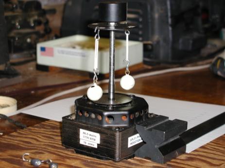
A spinning system was set up for doing experiments to demonstrate the rotating mass properties of inertia, gravitation, rotation, and precession. The carousel like apparatus allowed rotational “inertial mass” effects to be separated from those of gravitational mass. Additional experiments were run with single frame gyroscopes to confirm principles.
Howard Kober’s desire is to understand the created universe. He studied Classical Physics, Quantum Mechanics, and Relativity in his office and laboratory for over 50 years. He has done extensive experiments to clarify understanding and obtained patents in the field of rotational inertia, precession, and angular momentum.
Dale Crouse’s desire is also to understand the created universe. He studied chemistry, receiving his doctorate (Ph.D.) in 1970. Then, while supporting his family and seeking understanding of how the business enterprise works, he continued to broaden his study of the universe. Recently his interest has focused on understanding the unity between physics, chemistry, and life.
Anthony Talbot’s talent is as a scientific illustrator and cartoonist. Tony is centering his academic study on anthropology to gain credentials as a scientist. He has learned Wolfram Research’s Mathematica® to give mathematical accuracy to the theory and he also helped with the rotation experiments.
Levitating Mass® - copyright January 11, 2005
Experiment
Description Summary
Equitation
Rotation – Flexible Spoke & Lead Balls
Precession
Rotation – Single Frame Gyroscope
Mass
Distribution and Rotation Rate
Experiment Description Summary
Lead
Balls Spin Experiment
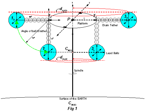
Starting with the balls orbiting the spindle, Fig 1, the centers of mass for the pair of balls, 1h and 3h, were in a plane parallel to the Earth (horizontal) that included the pivot point, P. The center of inertial mass for the rotating system of the two balls was also at P. The balls were separated by the diameter, dspin, and the tethers 1hT1 and 3hT3 were stiff. After stabilizing at 300rpm with a given energy and the rotation CounterClockWise (CCW) looking up from the Earth toward the rigid pivot point, an increase in energy to the spindle apparatus was converted into faster rotational velocity of the balls. The rotation rate was proportional to the amount of energy. Alternately, if the energy of a specific configuration of balls was held constant, but the length of the tether shortened, the balls rotated at faster than 300rpm and the rate (after stabilization) was inversely proportional to the tether length.
At a minimum energy supplied when the balls were rotating in the horizontal plane their rotational velocity was 300rpm, independent of their mass. The mass was varied from two ½ oz balls (1 oz total) to four balls at 48 oz each (12 pounds or 192 oz total). With further careful reduction in energy to the fan motor the spinning system moved through the transition zone between horizontal and vertical where the rotation rate slowed and the balls fell from the horizontal to the vertical. The rotating balls could be sustained at intermediate energy input, rotation rate, and specific ball & tether angle. This transition zone was from 300 rpm and an angle of 900 through energies that gave a minimum stable rotation rate of about 160-180 rpm and balls & tether angle down to about 650 to the spindle. This stable rotation rate and specific angle (or curvature to the path and circumference traveled per cycle), were also independent of the lead ball mass. Below these energies, the rotating system in the transition zone became unstable and the balls slowed their rotation and fell to vertical, an angle of 00, due the effects of friction and Earth’s gravity. The tethers remained stiff during the transition zone as if the balls could not advance or decline vertically or rotationally from a line extended out from the attachment point (T) that goes back through the platform to the pivot point (P). Changing the density of the balls from lead to plastic with the same dimensions, gave similar rates and angles. When dspin was increased from 20.7 cm to 33.2 cm by adding a bar above the platform, the balls became horizontal ~215 rpm instead of ~300 rpm.
In the vertical orientation, the balls were still orbiting the spindle at 60 rpm (once per second), the centers of mass for the pair of balls, 1V and 3V, are in a plane parallel to the Earth that includes the point CM(I). The center of inertial mass for the spinning system of the two balls was almost at CM(I) (slightly higher), the “at rest” position. The balls were separated by the diameter, drest, and the tethers 1VT1 and 3VT3 were stiff. Continuing to reduce energies, the balls slowed their rotation and came to a halt due to friction.
Key observations of equitation transition experiment from “at rest” to a stable state of levitation with added twist energy and then slowly back to “at rest” when the twist energy was removed:
- Tether portion of the rotating spoke rose as twist energy was added to the axis.
- All spokes reached horizontal at 300 rpm independent of amount of mass or mass density attached.
- The radius of the rotating system surface increased as the rotation rate increased.
- The tethers were always stiff at all times whether mass was attached or not.
- The tethers only bent at the spoke branch point in a vertical angle, not horizontal, keeping equal spacing between the tethers independent of mass on the tether.
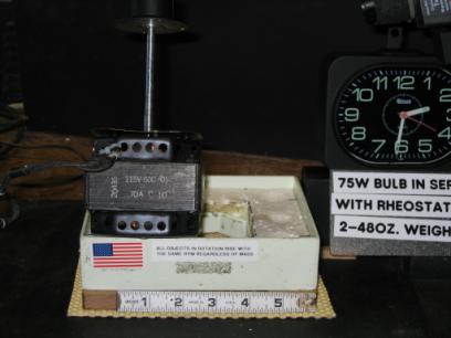
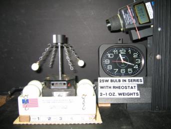
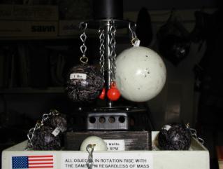
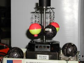
Four 3lb (48oz) or a total of 12 pounds of balls are spinning at 300 rpm
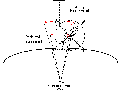
Gyro on String or Pedestal Experiment
The single frame gyroscope was rotated by pulling a wound string on the shaft[1]. The gyro was suspended at one pole either from the ceiling by a string or from the floor by a pedestal. In both cases when the rotation of the gyroscope rotor about its spin axis was between 300-450 rpm, the spin axis rotated (precessed) in the horizontal plane around the flexible pivot point at the North Pole of the gyro. As the rotation of the rotor gradually slowed down due to friction, the spin axis fell as far as possible toward the vertical from the horizontal while continuing to precess around the pole pivot point. When the direction of the rotor rotation was ClockWise (CW), the precession rotation was CounterClockWise (CCW). When the rotor stopped spinning, the gyroscope hung motionless from the string with the axis vertical.
Precession
Explanation of Precession is based around a description of Fig 1.14 in The Gyroscope Applied by K.I.T. Richardson. {redrawn as Fig 3 in this document}
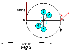
Fig 1.14 (Fig 3 here) ‘A single frame gyroscope when supported at N by a string will precess as shown at S by the dotted [red] arrow, due to the pull of gravity shown by the vertical [dotted black] arrow’.
A gyroscope precesses horizontally when the minimum angular momentum of the rotor is spinning less than 450 rpm near the surface of the Earth. Precession can be explained as the result of three torques, each torque manifested in one dimension of three dimensional space and all taking place at the same time. The Rotation Torque (1), the Gravitational Torque (2), and the Precession Torque (3) cause the inertial system to come into equilibrium with the gravitational system.
String Experiment
Three torque explanation applied to the single frame gyroscope.
The first torque (Rotation) {“intrinsic” inertial force torque} involves the spinning rotor creating angular momentum [blue cyclic arrow in Fig 4], and directing the gravitational force of the rotor to its axis. In the figure the rotor mass is shown in the form of 4 balls attached by spokes to the spin axis at the center of inertial mass CM(I) (red cross hatched circle).
The Rotation Torque was applied to the surface mass on the rigid spokes of the gyroscope. This caused curved motion in the y,z plane [i.e. surface mass moves from -z axis (1), to y axis (2), to z axis (3), to -y axis (4)]. The torque was applied in a tangential direction at the surface of the rotor, which was perpendicular to the attraction force communicated through the radial spoke from the center of inertial mass, CM(I) (red cross hatched circle). The Inertial Force was responsible for this torque.
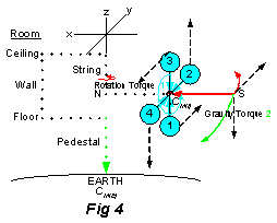
The second torque (Gravity) {gravitational force torque} results from the Earth’s gravity, CM(E) (the attraction force located in the center of Earth’s mass) pulling down on the gyroscope [green arrows] that was in a horizontal position, and was supported at one end by a string.
The Gravity Torque was applied at the end, S, of the gyro’s spin axis[2]. The Gravitational Force was responsible for this torque. This caused curved motion in the x,z plane (i.e. surface mass moves from -x axis to -z axis) . The torque was applied in the direction toward the center of gravitational mass (Earth) from the attraction force at the center of gravitational mass[3], through a complex path. The gravitational attraction force was communicated to the flexible branch point, N, through a path of molecules in the Earth mass system including the string[4]. It continued perpendicular (horizontal) from the branch point, N, through the inertial mass system by a path of molecules in the axis and then distributed at right angles to mass at the surface of the rotor by the molecules in the spokes, and finally continued along the axis to S.
The third torque (Precession) {“orbital” inertial force torque}occurs as a result of gravity pulling downward on the gyroscope, and the angular momentum of the rotor moving at right angles to this pull, that starts precession. As a result of this new rotation the gravitational force of the rotor (see footnote 3) will now be directed to the string, the center of this new rotation {branch point N in the figure}, or precessional mode.
The Precession Torque was also applied at the end, S, on the gyro’s spin axis. The Inertial Force was responsible for this torque in response to the Gravitational Force. This caused a cone shaped spiral curved motion for the axis {Fig 5, 6, & 7} in the x,y plane (i.e. surface mass from branch point N rotates from -x axis to y axis, to x axis, to -y axis) while the Rotation axis [red] moves through a right angle between horizontal[5] and vertical[6]. The torque was applied in a tangential direction at the axis end, S, which is perpendicular to the attraction force from the center of inertial mass and also perpendicular to the gravitational torque.
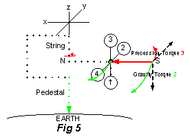
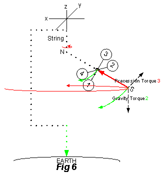
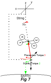
The Precession Torque 3 depends of the direction of rotation and will continue until the gyroscope’s rotation stops, and also depends on which end of the Rotation axis the string is placed. If the rotor rotation is clockwise looking from N, then the precession rotation is counterclockwise around the string at point N (as shown in Fig 5 looking up from the Earth). If the rotor rotation direction is reversed or the end where the string is attached is reversed i.e. attached at S vs N, then the precession will be clockwise. The radius of precession rotation was larger than the radius of rotor rotation (1 ¾ inch versus 1 1/8 inch) meaning the curvature of the rotation surface (S circumference) had less curvature for Precession torque (third) than the curvature for Rotation torque (first).
Equitation
A rotating mass system equitates[7] vertically when the minimum angular momentum of the rotor is spinning less than 450 rpm near the surface of the Earth.
Equitation can be explained as the result of three torques, each torque manifested in one dimension of three dimensional space and all taking place at the same time. The Rotation Torque (1), the Gravitational Torque (2), and the Equitation Torque (3) cause the inertial system to come into equilibrium with the gravitational system. Equitation motion appears as levitation.
Lead Balls Experiment
Three Torques explanation applied to the lead balls experiment
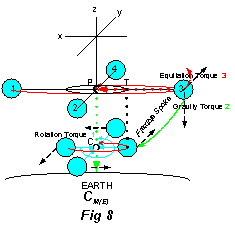
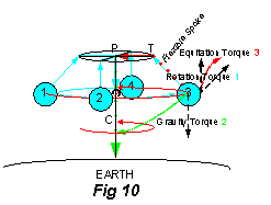
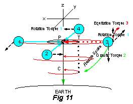
The first torque (Rotation) {“intrinsic” inertial force torque perpendicular to axis} was applied to the surface mass on the flexible spokes of the rotating mass. This caused curved motion in the y,x plane (i.e. surface mass moves from x axis (1), to -y axis (2), to -x axis (3), to y axis (4)). The torque was applied in a tangential direction at the surface of the rotor, which is perpendicular to the attraction force communicated by a complex path of molecules (C to P to T to Ball in Fig 8) through the flexible spoke from the center of inertial mass, CM(I) (red cross hatched circle). The Inertial Force was responsible for this torque.
The second torque (Gravity) {gravitational force torque} was also applied to the surface mass of the flexible spokes. The Gravitational Force was responsible for this torque. This caused curved motion in the x,z plane (i.e. surface mass moves from -x axis to -z axis) at the branch point, T, for the flexible spoke. The torque was applied in the direction toward the center of gravitational mass (Earth), through a complex path. The gravitational attraction force was communicated through a path of molecules from the Earth system to the rigid spin axis (spindle) and then the rigid point, P, the Pivot point for the inertial mass. Then the gravitational force was communicated in a perpendicular direction (horizontal) to the flexible branch point, T, and continued through the flexible spoke to the ball at the surface of the rotor.
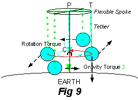
The third torque (Equitation) {“intrinsic” inertial force torque parallel to axis} was also applied to the surface mass of the flexible spokes. The Inertial Force was responsible for this torque creating a Levitation Force opposite to the Gravitational Force. This caused a cone shaped spiral curved motion for the spokes[8]{Fig 9, 10, & 11} in the x,y plane (i.e. surface mass connected at branch point T rotates from x axis (1), to -y axis (2), to -x axis (3), to y axis (4)) while the flexible spoke moves through a right angle between horizontal[9] and vertical[10]. The torque was applied in a tangential direction at the end of the spoke, which is perpendicular to the attraction force from the center of inertial mass and also perpendicular to the Gravity Torque. Since the Rotation Torque and Equitation Torque are applied perpendicular at the surface, the center of inertial mass, CM(I) (red cross hatched circle), levitates from C to P when the inertial force is turned on.
When the spoke reaches the equatorial plane, the third torque pushing the balls to the surface with the least curvature for the Inertial Force no longer causes vertical motion. The second torque was opposite to the third torque at all times while the rotor slowed down and stopped, and the rotating mass on the spoke fell toward the Earth in the Lead Ball experiment. Different, but similarly, in the Gyro experiment the second torque was perpendicular to the third torque at all times while the rotor slowed down and stopped, and the rotating system axis fell toward the Earth (Fig 12). The Inertial Force causing the equitation and precession torques, created a force in the opposite direction to the Gravitational Force and motion of the rotating mass, which diminished to zero as the rotation stopped. In precession the axis of the gyroscope moves, whereas in equitation the plane of the rotating mass at the surface spirals out toward the equator. At 300 rpm (5 revolutions per second), the precession or levitation force created by the rotating inertial mass system balanced the gravitational force of the Earth and the rotating mass became an independent mass system or frame of reference. The Precession Force angle to the spoke increased from zero when at rest becoming perpendicular to the Inertial Force toward the spin axis when the Inertial System was independent (horizontal).
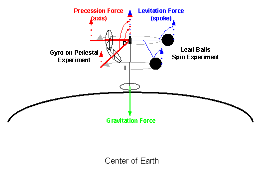
Fig 12 – Precession or Levitation
Forces
The Levitation (Equitation) Force angle to the spin axis in the flexible spoke increased becoming perpendicular to the Inertial Force when the Inertial System was independent (horizontal). Using “Gravitational Force” and “Inertial Force” as an attraction force located at the center of mass for Earth and the Rotating System respectively allowed an interpretation for the lead ball as well as the string suspended gyro experiments.
The path integral concept was used to track how the gravitational force was transmitted through mass atom by atom, or molecule by molecule. Only electrons of the subatomic particles have orbital angular momentum in atoms and are therefore carrying the gravitational message through the mass. The “path” result allowed linking together conceptually both experiments: where the rotating spin axis tethered to lead balls was perpendicular to the plane of the Earth, and the gyro spin axis held by the string was parallel to the plane of the Earth (Fig 12).
In all cases the torques 1 & 3, caused by the Inertial Mass, are perpendicular to the radial line toward the center attraction force of Inertial Mass, whereas torque 2, caused by the Gravitational Mass (Earth), is in the same direction as the radial line to the center attraction force of Gravitation Mass.
If the attachment to Inertial Mass was at the center of its mass, there would be “no gravity torque” and the mass would fall in a straight line to the surface of the Earth[11]. Because in these experiments the attachment is at a flexible “branch point” separated by a lever arm from the center of Inertial Mass, there is a torque. That the flexible branch point was at the end of the spin “axis” in the String experiment, and was along the “spokes” in the Lead Ball experiment was very interesting. The spin axis is known to keep its integrity including its absolute orientation in space. The flexible spokes also maintained an axis like character, linear between the surface and branch point along the spoke, and the whole spoke acted as a unit like the spin axis. This did not change the theoretical explanation, however, based on the attraction force at the frame of reference center, but did suggest new terminology was needed (equitation versus precession).
The radial dependence of rotation rate in the lead ball experiments had five seeming conflicting characters: (1) increasing rotation rate with increasing radius for equitation (or levitation) with increasing energy - Table IIa); (2) increasing rotation rate with decreasing radius of the platform – Table V; (3) increasing rotation rate with decreasing radius in the skater experiment (reducing the distribution of mass in space at constant energy – Table III); (4) increasing rotation rate at constant radius with increasing energy above equitation zone (radius or spoke constrained by structure of rotating mass); and (5) Up to the peak rotation rate, 215 rpm, an elastic tether (rubber band) in the flexible spoke[12], gave increasing rotation rate with increasing radius (Table VI) with increasing energy. In all cases the center of inertial mass moved to the least curvature for both the Inertial System and Gravitational System at a given energy and physical constraint due to structure.
There was
complexity in the results due to different experimental configurations that may
have introduced asymmetric friction effects like binding in the tether, or the
location of the break points. Balls on
the long spoke and the short spoke seemed to affect each other. There seemed to be vibrations or harmonic oscillations
both in the plane and along the axis in some experiments with very small mass
(1/2 oz). However, increasing rotation
with changing twist energy supplied by the fan motor during the equitation
stage of spin up or slow down seemed to give a consistent tangential velocity
of ~11 ft/sec (10.7-11.8 bolded italic in the Tangential Velocity
table) independent of mass or mass density when the mass just reached
horizontal and the inertial system became an independent frame of reference.
|
Spinning
Ball Experiment - Tangential Velocity |
||||||
|
|
calc |
Rotation |
|
calculated |
||
|
Radius |
2πR |
Rate |
|
velocity |
velocity |
velocity |
|
cm |
cm |
rpm |
Experiment - Table |
cm/min |
ft/sec* |
light
speed |
|
10.34 |
65 |
304 |
Skater - 2oz - Table III |
19,800 |
10.8 |
0.0000011% |
|
6.80 |
43 |
448 |
Skater - 2oz - Table III |
19,141 |
10.5 |
0.0000011% |
|
16.06 |
101 |
214 |
Skater - 2oz - Table III |
21,600 |
11.8 |
0.0000012% |
|
13.04 |
82 |
303 |
Skater - 2oz - Table III |
24,826 |
13.6 |
0.0000014% |
|
16.06 |
101 |
196 |
Skater - 16oz - Table III |
19,800 |
10.8 |
0.0000011% |
|
13.04 |
82 |
279 |
Skater - 16oz - Table III |
22,859 |
12.5 |
0.0000013% |
|
|
|
|
|
|
|
|
|
10.34 |
65 |
480** |
Repulsion - 1oz- Table I |
31,185 |
17.1 |
0.0000017% |
|
10.34 |
65 |
580** |
Repulsion - 3oz- Table I |
37,681 |
20.6 |
0.0000021% |
|
10.34 |
65 |
522** |
Repulsion - 16oz- Table I |
33,913 |
18.5 |
0.0000019% |
|
22.00 |
138 |
215** |
Elastic Tether - Table VI |
29,700 |
16.3 |
0.0000017% |
|
17.20 |
108 |
194 |
Elastic Tether - Table VI |
20,966 |
11.5 |
0.0000012% |
|
16.10 |
101 |
189 |
Elastic Tether - Table VI |
19,100 |
10.5 |
0.0000011% |
|
13.00 |
82 |
162 |
Elastic Tether - Table VI |
13,200 |
7.2 |
0.0000007% |
|
10.00 |
63 |
115 |
Elastic Tether - Table VI |
7,200 |
4.0 |
0.0000004% |
|
8.50 |
53 |
93 |
Elastic Tether - Table VI |
5,000 |
2.7 |
0.0000003% |
|
|
|
|
|
|
|
|
|
10.34 |
65 |
302*** |
Equitation - Table IIa (90) |
19,600 |
10.7 |
0.0000011% |
|
10.26 |
64 |
226*** |
Equitation - Table IIa (80) |
14,600 |
8.0 |
0.0000008% |
|
9.94 |
62 |
174*** |
Equitation - Table IIa (70) |
10,900 |
5.9 |
0.0000006% |
|
9.44 |
59 |
144*** |
Equitation - Table IIa (60) |
8,500 |
4.7 |
0.0000005% |
|
8.80 |
55 |
123*** |
Equitation - Table IIa (50) |
6,800 |
3.7 |
0.0000004% |
|
|
|
**excess
equitation energy
|
***
average of 4 |
|
*g
= 32.2 ft/sec2 |
|
This
complexity in our data, however, lends support to the idea that the energy
being supplied through the fan motor was only overcoming inertia and friction
but was not causing the balls to rotate or levitate. Rotation and Levitation seemed to be a property of the ball mass
itself (e.g. the motion of the atoms in the mass or motion of electrons in the
atoms) that was causing the inertial (as well as gravitational) response to the
attraction force.
The
gravitational response to the attraction force was a radial acceleration of
linear speed and acceleration toward more
curvature at the center of mass. The inertial response to the attraction force
was a tangential deceleration to less
curvature and increasing rotation rate as the radius increased during
levitation, but to a constant tangential linear speed (11 ft/sec) when the mass
just reached the equator of the rotating system. The radial response toward the center versus the tangential
response at the surface to the attraction force at the center of mass gave a
balance between attraction and repulsion tendencies (see footnote 12). Both
responses were independent of mass.
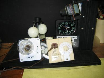
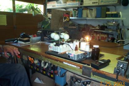
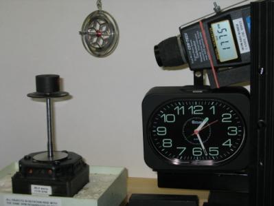
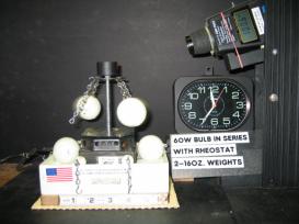
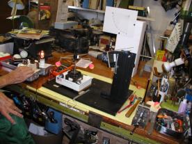
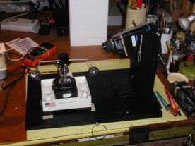
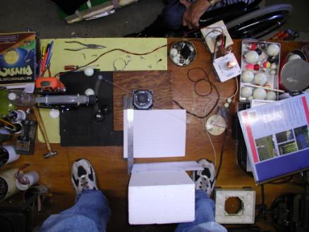
Spinning system with two balls, light bulb resistence, rheostat, tachometer
Fan motion, spinning axis with attached platform. Vertical white strip above platform was so tachometer could read rotation rate.
Overcome Friction.
A set of experiments illustrated that the minimum energy to overcome the friction in the apparatus gave the tethered mass a rotation of 160-180 rpm spin rate (angular velocity) at an angle of about 65o. Friction included the resistance to motion caused by moving metal parts against others of the apparatus and also air resistance to the moving balls. When the balls continue spinning at a steady rate, the drag due the apparatus had been overcome. Only the force of gravity and spin were acting on the tethered balls.
With less energy the balls would gradually slow down and come to rest at an angle of 0o. In this experiment, the length of the tether limited the effect of gravitational force and the balls hung vertically from the spindle platform. The balls did not reach (“touch”) the Earth when the spin motion stopped and only the gravitational force could cause them to move.
Mass Repulsion
Experiments indicated that a pair of balls rotate at about 50-60 rpm, in the vertical position. Below that twist on the spindle, the balls will not rotate. With more twist on the spindle, the balls move from a vertical toward a horizontal position in addition to increasing their rotation rate.
An experiment with one or two
spinning balls clarified the apparent repulsion tendency. First hook one ½ oz ball on the platform and
using a 30 watt bulb in the circuit with the rheostat, obtain the maximum
rotation rate. Measure the rotation
rate with a tachometer. Stop the
experiment by clicking off the switch, add a second ½ oz ball on the opposite
side of the platform and without changing the settings, click on the
switch. The rotation rate increased
rapidly to about 500 rpm and was still rising with the balls at 90o (perpendicular)
to the spindle when the test was stopped.
Then the experiment was repeated with a heavier set of balls (Table
I). When the ball weight reached 8oz,
the 30 watt bulb was removed to supply more twist energy to the spindle. What
caused the repulsion? The center of mass
of the rotating system was on the spindle for the two symmetrical spinning balls,
whereas the center of mass was displaced away from the spindle toward the one
ball. The friction on the ball bearings
of the fan motor was much greater with the asymmetric mass hooked to the
platform. With 2 or 4 balls symmetrically attached, the balanced connection
made no pull on the source of rotation i.e. the pivot point on the spindle.
|
|
|||
|
Ball Weight [Lead - mass = 207] |
Rheostat Settings |
Tachometer Reading Revolutions Per Minute |
|
|
One Ball unbalanced |
Two Balls balanced (2) |
||
|
½ oz |
9.5 (1) |
403 |
481 |
|
1 oz |
9.0 (1) |
269 |
480 |
|
3 oz |
6.5 (1) |
179 |
580 |
|
8 oz |
11.5 |
138 |
530 |
|
16 oz |
9.5 |
122 |
522 |
|
48 oz |
7.5 |
84 |
368 |
|
Notes: (1) 30W bulb in series with rheostat and motor (2) RPM increasing when test was stopped |
|||
Equitation Rotation – Flexible Spoke & Lead Balls
The steady rotation at an angle between 0o and 90o is considered equitation rotation. The balls make a cone with the pivot point at the base and the other end of the cone facing down.
As more energy is added, the balls move in two directions: (1) out and up (or away[13] from the Earth gravitational mass), spiraling to make a bigger circle and (2) tangentially increasing the rotation rate. The end of the transition zone occurs when the balls are horizontal in the equatorial plane and at an angle of 90o. The upper end angular velocity of the transition window was 300-315rpm. The lower end angular velocity of the stable transition window was about 165 rpm. Because the spiraling motion i.e. (1 above) was unexpected based on the theory of angular momentum that indicates only the tangential motion occurs from the torque i.e. (2 above), the moving out motion was further tested.
As the system spun up or slowed down, no difference was observed in the rise of these balls, therefore the length of the tether to the mass did not impact the movement out. All balls moved at the same angular velocity at a specific angle between 50o and 90o independent of the ball mass (Table IIa).
|
Table IIa – Equitation Rotation Experiment – Stable Energy Rotation Rates – Two Balls with rotation rate in rpm |
||||||
|
Mass of Balls oz. Each (X2 in grams) |
Energy I 0o Angle |
Energy II - 50o Angle |
Energy III - 60o Angle |
Energy IV - 70o Angle |
Energy V - 80o Angle |
Energy VI (*) 90o Angle |
|
½ (28)** |
0 |
125 |
142 |
172 |
220 |
299 |
|
8 (458) *** |
0 |
120 |
142 |
172 |
228 |
302 |
|
16(907) |
0 |
122 |
139 |
174 |
223 |
300 |
|
48(2722) |
0 |
123 |
150 |
177 |
234 |
306 |
|
*at Minimum to get horizontal rotation. ** Balls were dropping[14] ***plus two bobbers at ~2 grams each |
||||||
It took more energy to raise the heavier balls. The number of balls if paired and their weight, did not cause any ball to rise slower (spiral out to maximum). It appeared the center of mass of the spin system rose toward the pivot point as the torque increased. The torque being supplied to the spindle was levitating the center of the rotation system as a whole, both rotation angle and radius, independent of mass.
Equitation Rotation
A systematic look was made to determine what energy was required to levitate two balls to horizontal rotation (Table IIb). Horizontal rotation occurred for all weights when the angular velocity reached about 300 rpm.
|
Table IIb. Equitation Rotation Experiment – Two Balls – Horizontal rotation (4) energy. |
|||||
|
Light Bulb (1) |
30 watt |
40watt |
60watt |
75watt |
100watt |
|
Mass/Weight (3) |
Rheostat Setting
(2) |
||||
|
1 oz |
10 |
|
|
|
|
|
2oz |
9.5 |
13 |
|
|
|
|
8oz (½ #) |
7 |
11 |
|
|
|
|
16oz (1 #) |
5 |
9 |
11 |
11.5 |
|
|
32oz (2 #) |
|
6 |
9.5 |
10 |
|
|
40oz (2.5 #) |
|
|
8 |
9 |
|
|
48oz (3 #) |
|
|
7.5 |
8.5 |
9.5 |
|
Notes: (1) Light Bulbs provide a resistance so
energy can be adjusted in the circuit.
A smaller number of watts means less energy is supplied to the fan
motor. (2) A larger rheostat number
means less energy is supplied to the fan motor. (3) Two lead weight balls of the given weight were tethered on
opposite sides of the carousel spindle.
(4) 300 rpm |
|||||
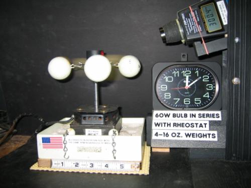
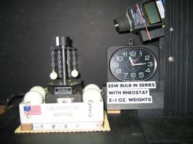
Horizontal Rotation – Four 16 oz Balls
Precession Rotation – Single Frame Gyroscope
Experiments with a single frame gyroscope were made to observe precession motion. The gyro was suspended from a string or supported on a pedestal at what is labeled as the north pole of the gyro axis. The gyroscopes rotor radius was 1 1/8 inch. The axis was 3.5 inches (N to S), so the precession rotation had a radius along the axis from North Pole (N) to the rotor of 1 ¾ inches. The string or pedestal provided the axis of rotation for precession.
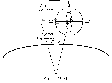
Pulling a wound string on the axis caused the rotor surface to move with positive curvature (Riemannian). When rotated around the axis in the clockwise direction as viewed from the North Pole pivot point, the whole gyro precessed in a plane horizontal to the Earth surface around this pivot point. The precession rotation was counterclockwise when the pivot point was at the North Pole (Fig 13), and clockwise when the pivot point was at the South Pole (Fig 14). The curvature of the precession rotation was negative (Lobachevskian) from the perspective of the center of attraction (frame of reference) of the gyroscope rotor. The precession motion of the gyroscope was perpendicular to the direction of gravitational attraction coming from the Earth frame of reference.
Suspended Single Frame Gyroscope
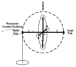
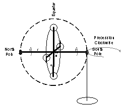
Fig 13 – North Pole
Pivot Fig 14 – South Pole Pivot
When both ends of the gyro were supported on pedestals as an anti-couple (anti means gravitational force applied in the same direction versus couple where the forces applied at each pole are parallel in the opposite direction), the gyro moved in the direction marked equator in the bottom view (Fig 15). This motion is tangential to the Earth’s surface and perpendicular to the attraction between the two frames of reference[15], i.e. the gyroscope frame of reference (at center rotation) and the Earth’s frame of reference (at center of mass). The motion, if separated from the Earth, would be an orbit parallel to the curvature of the surface.
Pedestal for Single Frame Gyroscope
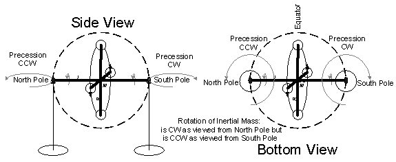
Fig 15 Anti-couple
Orbital Rotation
With full extension of the mass out from the pivot point on the spindle and held by the tether horizontally, the rotation rate was about 300 rpm. This was for all mass from two 2oz balls on the spindle to four 48oz balls on the spindle.
Increasing the input energy after the balls were rotating horizontally (at 300 rpm) just increased the angular velocity. There was no additional component of motion either vertical or radial. This is the textbook motion for angular momentum i.e. tangential motion at the surface of a spinning system that is perpendicular to the force.
Mass Distribution and Rotation Rate
A spinning woman ice skater is often used to
illustrate how reducing the mass distance from the spin axis, at constant
angular momentum, causes the system to increase its rotation rate. Since the rotation rate (angular velocity)
increased in the Equitation Rotation experiment as the lead balls moved farther from the spin axis toward
the equator, an experiment with this carousel apparatus was made to determine
if the apparatus gave the same result as the spinning ice skater. As seen in Table III, when the power setting
were kept the same (i.e. constant angular momentum), decreasing the radius from 10.3 to 6.8 cm (or 4L to 1L chain
lengths), caused the rotation rate to
increase from ~300 rpm to ~450 rpm.
|
Table III. Adjustable Tether Length Effect
(Spinning Skater Experiment) |
||||||
|
Two balls
on Spoke |
Tether
|
Radius* |
|
Power |
||
|
|
RPM |
Length* |
End
Ball |
|
volts |
bulb |
|
Short Spoke |
|
|
|
|
|
|
|
Initial 2 oz – 4L |
304 |
5.0 |
10.34 |
|
33.2 |
30W |
|
Alt - 3L |
347 |
3.8 |
9.14 |
|
33.0 |
30W |
|
Alt - 2L |
393 |
2.6 |
7.96 |
|
33.0 |
30W |
|
Alt - 1L |
448 |
1.4 |
6.80 |
|
33.0 |
30W |
|
Final 2 oz - 4L |
296 |
5.0 |
10.34 |
|
33.1 |
30W |
|
Long Spoke |
|
|
|
|
|
|
|
Long Spoke – 2oz – 4L |
214 |
5.0 |
16.06 |
|
34.5 |
30W |
|
Long Spoke – 2oz – 1L |
303 |
1.4 |
13.04 |
|
34.3 |
30W |
|
Long Spoke** – 16oz – 3L |
196 |
3.7 |
16.06 |
|
61.7 |
Short |
|
Long Spoke** – 16oz – 1L |
279 |
1.4 |
13.04 |
|
63.9 |
Short |
|
*Length and Radius (from
Spindle) in cm. Platform (Short) diameter = 5.1 cm, Rod (Long) diameter =
17.5 cm. **The Platform
(Short Spoke) also had two 1lb balls.
|
||||||
Equivalent Mass
The apparatus was placed on a scale to determine if the weight changed between the balls at rest and rotating. The scale was read while the balls were hanging vertically tethered and therefore only influenced by gravitational attraction. This gives the gravitational mass. The scale was read and recorded in both kilograms (kg) and ounces (oz.) – see Table IV. The fan motor was then turned on and the balls spun horizontally at 300 rpm, the minimum for total rotational inertia and independence from gravitation. This gives the weight of the rotational “inertia” mass. There was no difference. Even though with the heavy weights the apparatus was wobbling, the average position of the needle was unchanged from that of the balance when the balls were at rest.
|
Table IV. Gravitational and Inertial Mass Equivalence. |
||||
|
|
Weight* - kg |
Weight* – oz. |
Total Ball Weight - oz |
Average** Ball Weight – oz. |
|
Apparatus Alone |
2.100 |
74.5 |
|
|
|
Plus Two 2oz. |
2.220 |
78.5 |
4.0 |
2.0 |
|
Plus Four 2oz. |
2.360 |
83.5 |
9.0 |
2.3 |
|
Plus Four 16oz. |
4.040 |
142 |
67.5 |
16.9 |
|
Plus Two 40oz. |
4.400 |
155 |
80.5 |
40.3 |
|
Plus Two 48oz. |
5.360 |
174 |
99.5 |
49.8 |
|
*Read directly from the scale.
**Calculated |
||||
Mass Density
To determine if mass density impacted rotation rate and angle, two 8oz sinkers and two small bobbers of the same diameter were attached to the platform. Both rose at the same angle and rotation rate (See Table IIa for data).
Bobbers and Sinkers levitate at the same angle and rate.
Platform Diameter
To determine if the diameter of the
platform to which the tethers were attached impacted rotation rate and angle, a
17.5 cm diameter rod (long spoke) was screwed on above the #2 and #4 attachment
points of the 5.0 cm diameter platform (short spoke). Two bobbers were spun up to horizontal at ~ 200 rpm. Then to
confirm this result, two 2 oz balls were placed on the short spoke and two on
the long spoke. The long spoke mass
reached horizontal at 218 rpm and the short spoke mass reached horizontal at
300 rpm (Table V). Increasing the
length of the spoke (platform to rod), reduced the rotation rate to reach
horizontal. The experiment was repeated
with 16 oz balls (1lb). Equitation
similar to the Short (Platform) Spoke were observed on the Long (Rod) Platform
but at a lower rotation rate to reach horizontal.
|
Table V – Platform Diameter Experiment – Equitation Rotation – Two Balls with rotation rate in rpm |
||||
|
Mass of Balls oz. Each (gramsX2) |
Energy III - 60o Angle |
Energy IV - 70o Angle |
Energy V - 80o Angle |
Energy VI (*) 90o Angle |
|
2 oz (28) |
101 |
122 |
151 |
216 |
|
16 oz (907)** |
106 |
130 |
173 |
216 |
|
2 oz (28) ** |
94 |
115 |
162 |
218 |
|
Reference 16 oz (907)*** |
139 |
174 |
223 |
300 |
|
*at Minimum to get horizontal rotation – radius at horizontal = 16.60 cm **also has mass rotating on platform – radius at horizontal = 10.34 cm ***Two 1lb balls - platform experiment Table IIa |
||||
Bobbers on Long Spoke (Rod) Long rod -1lb, Short platform - ½ lb
Equitation Symmetry
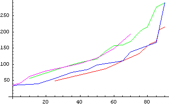
Is the levitation during the power up of the lead ball experiment, until the balls are rotating in a horizontal plane, symmetrical to the fall of the balls when the power is turned off? The balls rise from the pole to the equator (equitation) during power up increasing their angle with respect to the spindle from 0 to 90 degrees. As they rise the rotation rate increases to 300 rpm. When the power is turned off the balls fall back and reduce their rotation rate. The following graphs indicate that the rise during power up and fall when the power is turned off are symmetrical
For the following graphs, 2 oz. Weights were used on both the long and short spokes.
The
Equation for making a graph in Mathematica®:
ListPlot[{{![]() ,
, ![]() }, {
}, {![]() ,
, ![]() }, … }]
}, … }]
For the following graphs X = angle in degrees, Y = rotation in Revolutions Per Minute (rpm).
The
Equation for combining two graphs in Mathematica®:
Show[a,c]
Longspoke:
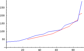
The red line represents the weights increasing in speed and angle (Power up)
The blue line represents the weights decreasing in speed and angle (Power Off)
(putting data into the equation)
a=ListPlot[{{25,48},{55,85},{60,98},{65,110},{70,122},{75,133},{80,156},{82,163},{85,170},{87,207},{90,214}},PlotJoined®True,PlotStyle® RGBColor[1,0,0]]
a=The redline(RGBColor=1,0,0)
c=ListPlot[{{90,291},{85,167},{70,138},{65,111},{50,98},{45,84},{35,74},{25,56},{15,40},{0,34}},PlotJoined®True,PlotStyle® RGBColor[0,0,1]]
c=The blueline(RGBColor=0,0,1)
Shortspoke:
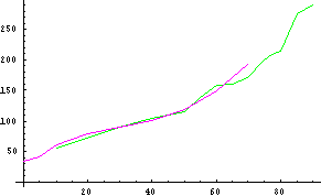
The green line represents the weights increasing in speed and angle (Power Up)
The purple line represents the weights decreasing in speed and angle (Power Off)
b=ListPlot[{{10,56},{30,90},{40,105},{50,116},{55,140},{60,158},{65,160},{70,170},{75,200},{77,209},{80,215},{85,276},{90,291}},PlotJoined®True,PlotStyle® RGBColor[0,1,0]]
b=The greenline (RGBColor=0,1,0)
d=ListPlot[{{70,192},{60,149},{50,120},{40,102},{30,91},{20,79},{10,62},{5,41},{0,34}},PlotJoined®True,PlotStyle® RGBColor[1,0,1]]
d=The purpleline (RGBColor=1,0,1)
(combining
the 2 graphs in Mathematica®)
Show[a,b,c,d]
Long and Short spoke:
Elastic Flexible Spoke
The radial dependence of rotation rate in the lead ball experiments had four seeming conflicting characters: (1) increasing rotation rate with increasing radius for equitation (and levitation) with increasing energy - Table IIa); (2) increasing rotation rate with decreasing radius of the platform – Table V; (3) increasing rotation rate with decreasing radius in the skater experiment (reducing the distribution of mass in space at constant energy – Table III); and (4) increasing rotation rate at constant radius with increasing energy above equitation zone (radius or spoke constrained by structure of rotating mass). Using an elastic tether (rubber band) in the flexible spoke gave the results in Table VI. The peak rotation rate, 215 rpm, at 22.0 cm/850 angle/34.1v.was equivalent to the Long (Rod) Spoke rotation result at 16.6 cm/900 angle/34.5v and Short (Platform) Spoke results at 10.0 cm/750 angle/30.9v or 9.0 cm/800 angle/33.1v. i.e. like (1) above increasing rotation rate with increasing radius (Table VI). The hook tether did not appear to move to a full 900 angle possibly due to binding with the hole. The maximum angle, 850, was achieved at 197 rpm.
Two 1 oz balls on
Elastic Tether – At Rest – Side View
|
Table VI. Elastic Tether Length Effect |
||||||
|
Two 1 oz balls on Elastic Spoke from
Platform |
Radius* |
|
Power |
|||
|
Radius Equivalent |
RPM |
Angle,
0 |
End
Ball |
|
volts |
Setting** |
|
|
0 |
0 |
8.5,8.7 |
|
|
|
|
|
85 |
45 |
|
|
31.1 |
12 |
|
Platform+4L/2oz+800 |
93 |
55 |
8.5 |
|
31.1 |
|
|
|
107 |
60 |
9.0 |
|
31.1 |
|
|
Platform+4L/2oz+900 |
115 |
70 |
10.0 |
|
31.1 |
|
|
|
128 |
75 |
10.8 |
|
31.1 |
|
|
|
152 |
80 |
12.3 |
|
31.6 |
11.5 |
|
Rod+1L/2oz++900 |
162 |
82 |
13.0 |
|
32.1 |
11.0 |
|
|
180 |
82 |
14.5 |
|
32.2 |
10.5 |
|
|
185 |
|
15.3 |
|
32.9 |
|
|
Rod+4L/2oz++900 |
189 |
|
16.1 |
|
33.3 |
|
|
|
194 |
85 |
17.2 |
|
33.2 |
|
|
|
200 |
|
19.0 |
|
33.7 |
9.0 |
|
|
206 |
|
20.0 |
|
34.0 |
8.0 |
|
|
212 |
85 |
21.0 |
|
34.2 |
7.0 |
|
|
215 |
85 |
22.0 |
|
34.1 |
|
|
*Radius (from
Spindle) in cm. Platform (Short) diameter = 5.1 cm, Rod (Long) diameter =
17.5 cm. **Rheostat setting
with 30 watt bulb |
||||||
![]()
Elastic Tether – Two 1 oz Balls – Top View
![]()
![]()
![]()
Two 1 oz balls on Elastic Tether
![]()
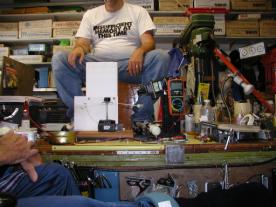
Howard Kober – Martin Talbot – Dale Crouse
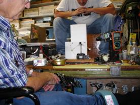
Tony Talbot and Howard Kober
Inertia – A property of mass that is resistance to change in motion.
Speed - distance per unit time (linear velocity i.e. without direction).
Velocity – distance per unit of time in a direction with respect to a frame of reference. Represents both speed and direction.
Rotation – Continuously changing direction.
Pivot Point – A fixed point around which something turns (a frame of reference).
Acceleration – change of velocity (either speed or curvature) per unit of time. Acceleration is the change per unit of time of the speed, the curvature of the curve (per unit of time?), and includes the act of rotation.
Mass – Mass is the quantity of matter in an object. Mass measures (1) How much gravity it exerts on other objects and (2) How much it resists acceleration, how much inertia it has.
Weight – The gravitational force on an object. Weight varies according to where you are: in deep space, your weight may be zero, but your mass is the same wherever you go!
Rotational Inertia (mass on a curve) - means that force is required to start rotation. Rotational inertia resists rotational acceleration and is the rotational analog of mass. Once started, however, mass will continue to rotate forever in the absence of friction.
Angular Velocity (moving on a curved path) -means the turning rate, e.g. revolutions per minute, and that the acceleration is at a right angle to the velocity direction and the force is directed toward the center of rotation.
Force – The phenomenon that causes an object to accelerate by changing speed.
Torque – Torque is the rotational analog of force. Torque causes an object to accelerate by changing direction but can also change speed. In rotation the direction of motion caused by torque is perpendicular to the radius. Internal torque is applied at the axis and External torque is applied at the surface.
Couple – Applying equal force in the opposite direction on the north and south axis of a rotating system.
Gravity - An attractive force that exists between any two masses. Gravity produces acceleration. All objects fall with the same acceleration, regardless of mass.
Universal Gravitation – The gravitational force between two masses M and m is proportional to the product of the masses and inversely proportional to the square of the distance separating their centers of mass.
Levitation –to rise in the air by overpowering gravity
Momentum and Impulse – mass times velocity = momentum and change in momentum = impulse. Momentum is conserved in the absence of an external force.
Angular Momentum
- rotational inertia times angular velocity. Angular Momentum is conserved in
the absence of an external Torque
Precession – A slow gyration of the rotation axis of a spinning body in the presence of a torque.
Equitation – A spiraling motion of surface mass and spokes from the poles toward the equator of a spinning system in the presence of a torque.
Gyroscope – a spinning rotor or wheel suspended in gimbals.
Gimbal – a frame with bearings for holding the
rotational axis of a gyroscope.
Radius – distance from the center of mass to the surface.
Sin and Cos
(sine and cosine) –see Fig 16
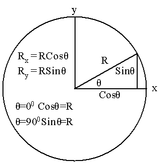
Fig 16 – Angle Trigonometry
|
Figure # |
Page |
Figure Name |
Tab Location in Levitating Mass-12312004.vsd |
|
1 |
5 |
Lead Balls Experiment |
Lead Balls Experiment |
|
2 |
7 |
String Experiment |
String Experiment |
|
3 |
8 |
The Applied Gyroscope – Gyroscope |
Gravity-Inertial |
|
4 |
8 |
String Exp. - Definitions |
Gravity-Inertial |
|
5 |
10 |
String Exp. - Horizontal - Torques |
Precession vs Gravity Torque |
|
6 |
10 |
String Exp. - 450- Torques |
Precession vs Gravity Torque |
|
7 |
10 |
String Exp. - No Spin - Torques |
Precession vs Gravity Torque |
|
8 |
11 |
Ball Exp. - Definitions |
Torque Planes |
|
9 |
12 |
Ball Exp. - At Rest - Torque |
Equitation Levitation |
|
10 |
12 |
Ball Exp. - 450 - Torques |
Equitation Levitation |
|
11 |
12 |
Ball Exp. - Horizontal - Torques |
Equitation Levitation |
|
12 |
13 |
Precession or Levitation Forces |
Precession - Levitation |
|
13 |
22 |
Pedestal - North Pole |
Precession – Pole |
|
14 |
22 |
Pedestal – South Pole |
Precession – Pole |
|
15 |
23 |
Pedestal – Anti-Couple |
Precession - -Anti-Couple |
|
16 |
33 |
Angle Trigonometry |
Spokes-Cyclinder |
The Gyroscope Applied – by K.I.T. Richardson - Copyright 1954 - Published by The Philosophical Library.
The Cartoon Guide to Physics – by Larry Gonick & Art Huffman – Copyright 1990 – Published by Harper Perennial in 1991.
The Feynman Lectures on Physics – Three Volumes – by Feynman, Leighton, and Sands Commemorative Issue – Copyright 1963,1989 by California Institute of Technology – Originally Published in 1963-1965 by Addison-Wesley Publishing Co.
The Evolution of Physics – by Albert Einstein and Leopold Infeld – Copyright 1936 and 1966 – Published by Touchstone Books (Simon & Schuster, Inc)
Essays in Science – by Albert Einstein - Copyright 1934 – Published by The Philosophical Library – Originally these were included in “The World as I See It”
Relativity – by Albert Einstein – Copyright 1961 – Published by Three Rivers Press (Random House, Inc)